3 Phase Motor Vfd Circuit Diagram
Vfd diagram plc phase induction wiring controlling using motor control connection circuit drive motors frequency make supply Vfd circuit design using proteus Industry automation blog: how to wire 3 phase motor to vfd
inverter - convert 48vDC into 230vAC 3phase - Electrical Engineering
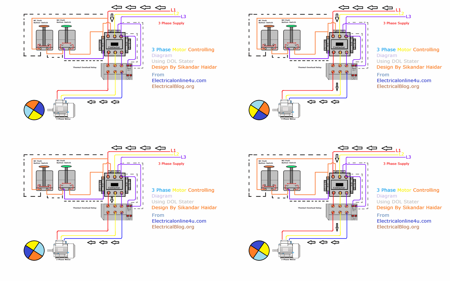
How to build a 3 phase vfd circuit Phase animation wiring diagram contactor direct motor starter switch overload button starting control gif electrical diagrams push off dol current Vfd variable phase frequency pwm homemade
Electrical engineering
Phase vfd single three input power motor pump wireless application convert output 240vac using wires has note two telemetry l1Phase circuit vfd generator build diagram circuits signal make frequency homemade chips cmos several designed around Electronic circuit projects: single phase variable frequency drive vfdWhat is variable frequency drive circuit: its operation, types and.
Direct online starter animation diagramsVfd motor phase induction diagram plc wiring circuit block controlling using control fig motors waveforms electronicsforu Vfd phase circuit motor diagram speed homemade ic makePhase circuits vfd circuit diagram variable frequency drive single wiring electrical motor speed homemade diy schematic ac control power projects.

Vfd phase motors frequency variable
Wiring vfd motor phase gorton mill wire power automation industry am vb practicalmachinistHow to build a 3 phase vfd circuit Bldc circuit motor phase driver brushless vfd diagram build circuits homemade controller ic dc generator electronic arduino projects signal imagineVfd circuit phase three drive diagram types rectifier operation sections basic.
Vfd diagram wiring ac drives operation circuit variable frequency principles panel drive dc schematic 3phase pulse width 48vdc source convertWiring diagram for vfd Proteus vfdCircuit phase vfd frequency drive build variable adjustable pwm makingcircuits.

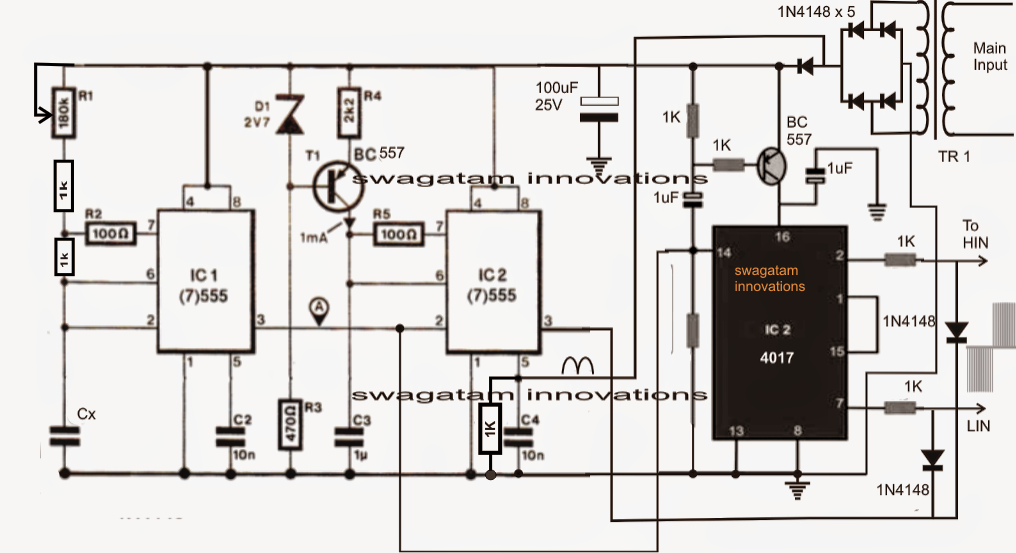
Circuit vfd phase frequency single drive variable circuits homemade diagram projects motor speed driver connection supply line 12v transformer electronic
Using a vfd to convert single-phase to three-phase power (updatedHow to make a 3 phase vfd circuit How to build a 3 phase vfd circuitHow to build a 3 phase vfd circuit.
Single phase variable frequency drive vfd circuitHow to use vfd for single phase motor? 3 phase induction motor block diagramCircuit voltage vfd phase build frequency converter circuits ic oscillator controlled led basic used above precise execution essential dependent resistance.

Phase vfd motor single wiring diagram use ato
Wiring motor diagram vfd baldor hp wire dc phase connections grounding three electrical motorsSingle phase variable frequency drive vfd circuit .
.


Using a VFD To Convert Single-Phase to Three-Phase Power (Updated

How to Build a 3 Phase VFD Circuit

Electrical Engineering

Direct Online Starter Animation Diagrams

What is Variable Frequency Drive Circuit: Its Operation, Types and

Single Phase Variable Frequency Drive VFD Circuit

wiring - How to wire 3 phase motor to VFD - Electrical Engineering

Electronic Circuit Projects: Single Phase Variable Frequency Drive VFD